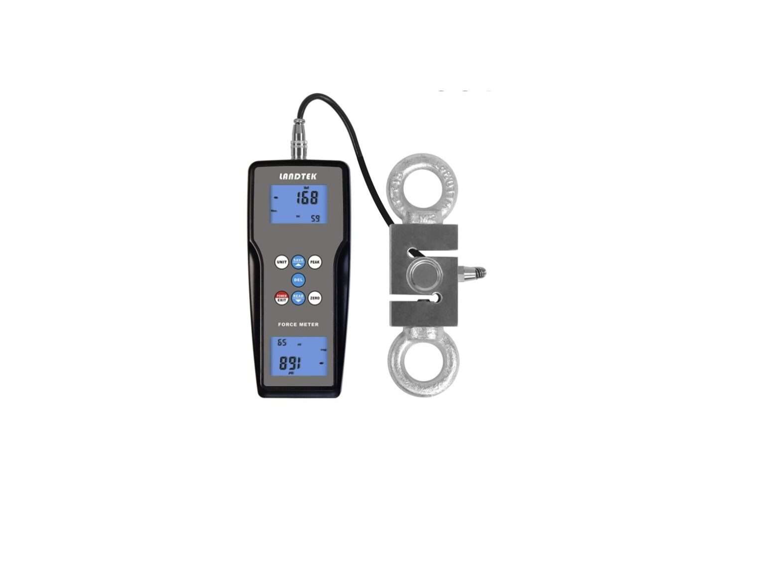
LANDTEK Digital Force Gauge FM-207 User Manual
1. INTRODUCTIONS
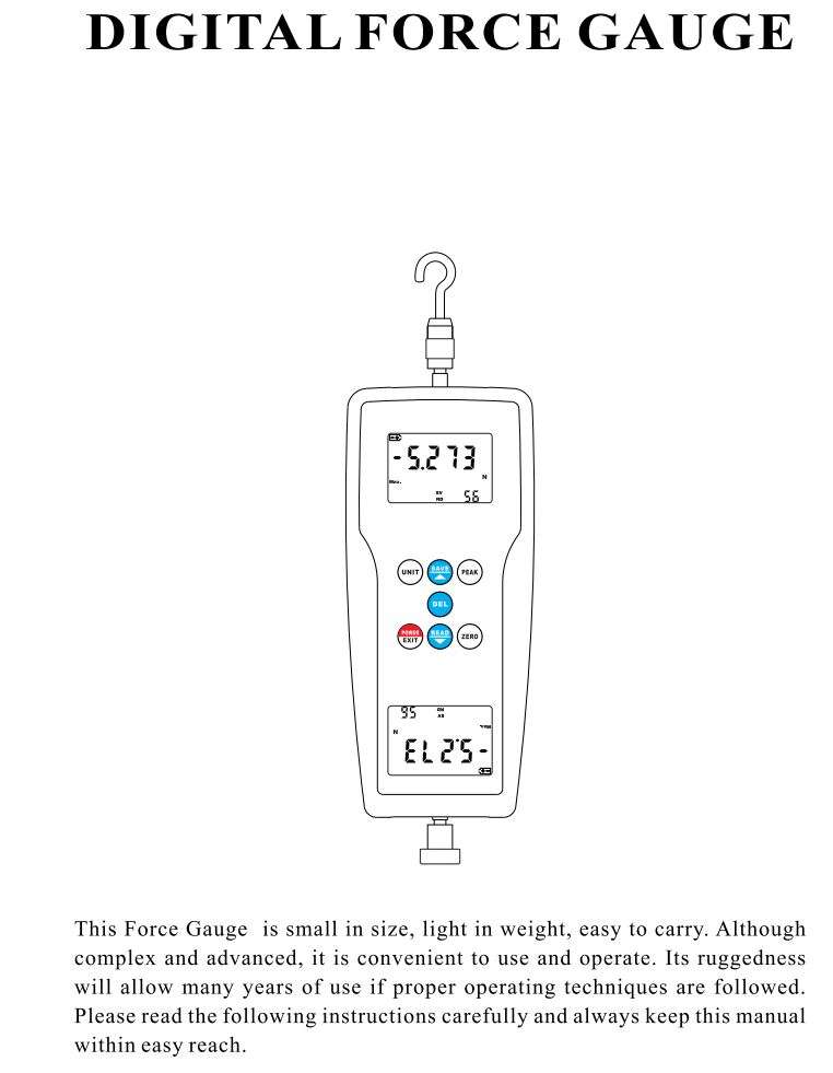
FM-207 series force gauge is the latest designed force gauge, which is researched and developed by our company. It has the advantages of high accuracy, easy operation and easy to carry. It has the peak value hold function. The measurement data can be memorized into the gauge or transmitted to the computer for statistical analysis. Being installed with a variety of test bench and fixture, it can become a test machine for different uses.
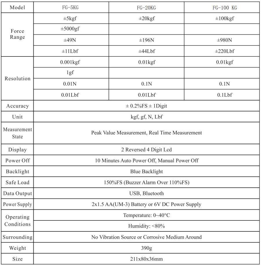
The digital force gauge has a number of models with different force range for the user to choose, the user can select the appropriate model according to the force of tested products. The scientific test method is to use 10%~ 100% of the full test range. The measurement department recommends not to use <l % of the full test range. Before testing, when the instrument and the test object have been in place, press ZERO key to clear the load of the fixture.
The digital force gauge is a kind of simple and convenient multifunctional instrument for high-accuracy push force and pull force test. It is widely used in electronics, building hardware, textile, auto parts, ignition device such as lighter, fire fighting equipment, pen manufacturing, lock manufacturing, fishing gear, chemical, power machinery, scientific research institutions and other industries. For the push and pull load test, plug and unplug force test and destructive test etc. With digital display, high resolution, high sampling speed, easy testing procedure, it is an efficient and high-accuracy instrument for push force and pull force test in the new generation.
2. FUNCTIONS AND FEATURES
- High accuracy and high resolution.
- Digital display with no guessing or errors.
- With 4 measurement unit for selection and conversion, N, kg, lb, g.
- With peak value hold function.
- With data memory function, can memorize 99 groups of data.
- With data output function. Measurement data can be transmitted to computer by USB cable or Bluetooth adapter for various analysis.
- With 10 minutes auto power off and manual power off.
- Power can be supplied by either alkaline battery or 6V DC power.
3. TECHNICAL PARAMETERS
4. STRUCTURE DESCRIPTION
4.1 Overall Structure
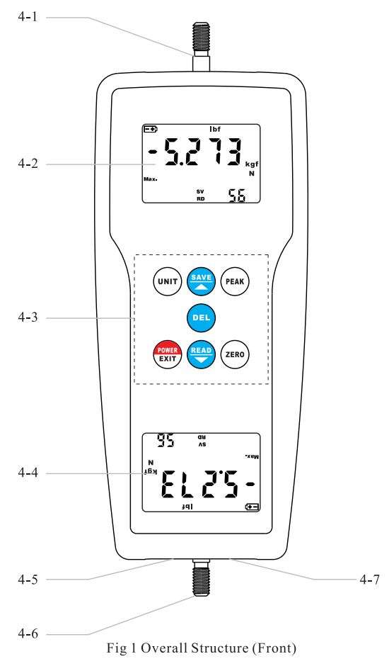
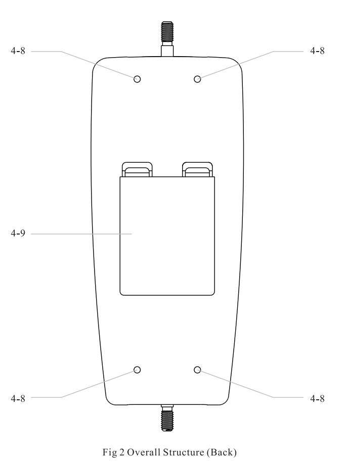
Function Description Of Overall Structure
4-1 Sensing Screw
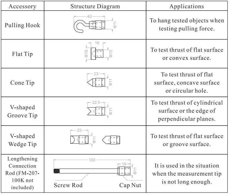
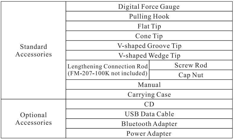
The screw is the main force sensing structure component of the whole instrument. The function of the screw is to conduct the outer applied force into the gauge. It can be connected with accessories such as the pull hook, the flat measurement head, the conical measurement head, the V shape groove measurement head, the V shape wedge measurement head, the lengthening connection rod, etc. For details of accessories, see page 12.
4-2 Display A
It is used to display the readings of measurement, units of measurement, the indications of the operation, etc.
4-3 Operation Key Area
All operation keys are distributed on this area. Thus, all keys of the gauge can be found here.
4-4 Display B
It is also used to display the readings of measurement, units of measurement, the indications of the operation, etc. It is designed for more convenient reading on multiple directions.
4-5 USB Cable Interface
It can be connected with the USB data cable, to achieve the function of data collection with the data acquisition software.
4-6 Fixing Screw
It is the fixing component of the instrument, used for fixing the instrument with other extra components.
4-7 Power Interface
It can be connected with 6V DC Power for power supply.
4-8 Fixing Screw Holes
It is also the fixing component of the instrument, used for fixing the instrument with other extra components.
4-9 Battery Case On The Back
The place to install batteries, for battery supply.
4.2 Display
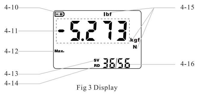
Function Description Of Display
4-10 Battery Indicator’ 🔋 ‘
When the battery voltage is low, ‘ 🔋 ‘ comes on the top left corner of the display, indicating it is lack of voltage and the batteries need to be replaced.
4-11 Displayed Reading
In this gauge, the pushing force is a positive value (not shown”+”); the pulling force is a negative value (display”-“).
4-12 Peak Value Indicator MAX.
When the indicator ‘MAX.’ comes, it indicates that it is in Peak Value Hold Mode, in which the displayed reading is the peak value during measurement. When the indicator ‘MAX.’ does not come, it indicates that it is in Real Time Measurement Mode, in which the displayed reading changes according with the applied load.
4-13 Memory Indicator SV
When ‘SV’ comes, it indicates that it is in measurement mode, in which the displayed reading can be memorized into the gauge.
4-14 Scanning Indicator RD
When ‘RD’ comes, it indicates it is in Data Scanning Mode, in which the displayed value is one of the data in memory.
4-15 Measurement Unit
It indicates the current measurement unit, which includes ‘kgf’, ‘gf’, ‘N’, ‘lbf’.
4-16 Amount Of Datas In Memory/ Serial Number Of Data
In the Measurement Mode, it indicates the amount of datas in memory, for example ‘ 56 ‘. While in the Scanning Mode, it indicates ‘Serial Number Of Data/ Amount Of Datas In Memory’, for example’ 36/56 ‘.
4.3 Operation Key
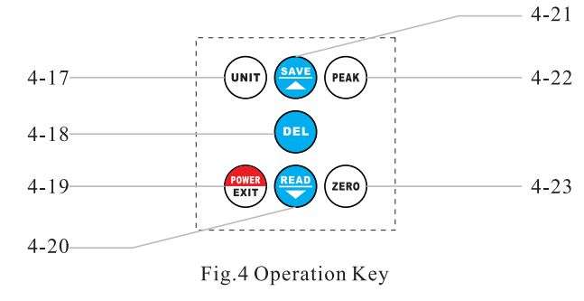
Function Description Of Operation Key
4-17 Unit Conversion Key(UNIT)
It is the key for unit conversion.
4-18 Delete Key(DEL)
It is the key for deleting the memorized datas.
4-19 Power/Exit Key(POWER/EXIT)
It is the key for powering on/off the gauge. Also, it is the key for exiting from Data Scanning Mode. What’s more, it is the key for going into the Auto Power Off Settings.
4-20 Read/Downward Key(READ/ T)
It is the key for entering the Data Scanning Mode, the key for transferring datas form the gauge to computer, the key for downward scanning in Data Scanning Mode, the key for time conversion in Power Off Setting Mode.
4-21 Save/Upward Key(SAVE/ _.)
It is the key for memorizing datas, the key for upward scanning in Data Scanning Mode, the key for time conversion in Power Off Setting Mode.
4-22 Peak Value Key(PEAK)
It is the key for conversion between the Peak Value Hold Mode and the Real Time Measurement Mode.
4-23 Zero Key(ZERO)
It is the key for zero calibration of the gauge.
5. POWER ON & POWER OFF
5.1 Power On
Install the batteries correctly or plug in the DC power supply. Then press the Power/Exit Key(POWER/EXIT) to power on the gauge.
5.2 Power Off
5 .2.1 Manual Power Off
In the state of power-on, press and hold the Power/Exit Key
(POWER/EXIT) for about 2 seconds, the indicator ‘ OFF ‘comes out. Then release the key, the gauge is powered off.
5 .2.2 Auto Power Off Auto power off function can be activated by user. When it is activated, the gauge will be powered off automatically after 10 minutes with no key operation. For details, please refer to 15 Setting Auto Power Off.
6. CALIBRATION
Install the gauge at the position of measurement according to the requirements. Then press the Zero Key (ZERO) to calibrate the gauge, the value of0 comes out on the display.
* When the weight of the used fixture is more than 20% of the range, or the load of the gauge is more than 20% of the range, the gauge is not able be calibrated. In this case, it is necessary to use a lighter fixture or remove the load, then calibrate.
7. REAL TIME MEASUREMENT MODE & PEAK HOLD MODE
Two kinds of measurement modes can be set for this gauge, the Real Time Measurement Mode and the Peak Hold Mode.
When there is no peak indicator “MAX” on the display, it is in the Real Time Measurement Mode. The displayed test value changes according to the load.
Press the Peak Value Key (PEAK), the peak indicator “MAX” comes out on the display. It is in the Peak Hold Mode. The displayed test value is the maximum value during the measurement.
8. DATA MEMORY
When the gauge is in measurement mode, the memory indicator ‘SV’ is display. Press the Save/Upward Key (SAVE/▲), the displayed data will be memorized in the gauge, the amount of datas in memory plus one. The gauge can store up to 99 sets of measured data.
9. DATA SCANNING
After a certain amount of datas are memorized in the gauge, press Read/ Downward Key (READ/ ▼) to enter the Data Scanning Mode. The memory indicator’ SV’ disappears while the Scanning Indicator ‘RD’ comes out on the display. Also, the present memorized data and the ‘Serial Number Of Present Data/ Amount Of Datas In Memory’, such as ’36/56 ‘, comes out on the display. Press the Save/Upward Key (SAVE/▲) or Read/Downward Key (READ/ ▼) for data switching. To exit the Data Scanning Mode, just press the Power/Exit Key (POWER/EXIT).
10. DATA DELETING
In the Data Scanning Mode, press the Delete Key (DEL) to delete the present data. In measurement modes, press and hold the Delete Key (DEL) for about 3 seconds, all of the memorized datas will be deleted.
11. THE INSTALLATION OF CONNECTION SOFTWARE
installation steps are as follows, for details, please refer to the demo video and documentation in the CD.
→ Run the CD, open the compressed folder, double click the ‘Test Setup. Cn’.
→ Click ‘Next’.
→ Click ‘Browse’, select the installation position, click ‘OK’.
→ Click ‘Next’.
→ Click ‘Install’.
→ Click ‘Finish’.
12. DATA TRANSMISSION FUNCTION
After the installation of connection software, plug in the USB Data Cable or the Bluetooth Adapter, then install the device on the computer. For the installation steps of device, please refer to the demo video and documentation in the CD.
13. REAL TIME DATA TRANSMISSION FUNCTION
After the installation of connection software, plug in the USB Data Cable or the Bluetooth Adapter, then install the device on the computer. For the installation steps of device, please refer to the demo video and documentation in the CD.
14. UNIT CONVERSION FUNCTION
In either Real Time Measurement Mode or Peak Hold Measurement Mode, press the Unit Key (UNIT) for measurement unit conversions.
15. SETTING OF AUTO POWER OFF
When the gauge is powered on, press and hold the Power/Exit Key (POWER/EXIT) for about 3 seconds. Release the key when the indicator ‘ RUr0· (AUTO) comes out on the display.
A figure, ‘ 10 ‘or’ 0 ‘, comes out on the display. Respectively indicating auto power off in 10 minutes with no key operations and non-auto power off. Press the Save/Upward Key (SAVE/_.) or the Read/Downward Key (READ/ ▼ ) to convert between these two settings. Press the Power/Exit Key (POWER/EXIT) to quit.
16. INSTALLATION & MEASUREMENT
Power on the gauge, press operation keys to select the intended measurement mode according to the need, or measure directly with the factory default settings.
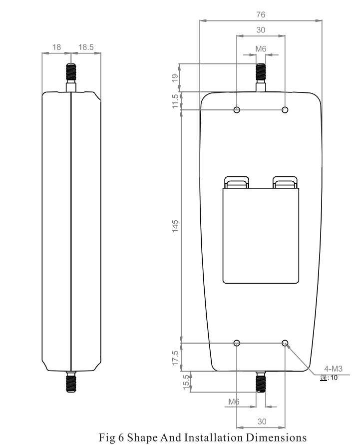
- Select appropriate test fixtures to install on the force gauge (to use self-made fixtures, please refer to the relevant data’s on the next page ‘Shape And Installation Dimensions’).
- When measuring, please hold the force gauge firmly or install it on a suitable test machine. Please make the force and the sensing rod in a straight line, so that measurements of load are accurate.
- After the measuring, remove the load, turn off the gauge, remove the fixtures, and then put the items back in the tool box after cleaning, in order to prepare for the next use.

17. BATTERYREPLACEMENT
17 .1 When it is necessary to replace the battery, the battery symbol will appear on the Display.
17 .2 Slide the Battery Cover away from the gauge and remove the batteries.
17 .3 Install new batteries correctly into the case.
17.4 If the gauge is not to be used for any extended period, remove batteries.
18. SECURITY AND CAUTIONS
18.1 Cautions
- If the operation is incorrect, it is possible to damage the gauge or cause serious accident. In the manual, the important items of accident prevention and measurement procedure of the gauge are pointed out. Please read this manual carefully before measurement, keep it properly after reading, in preparation to read again.
- If it is to test the impact load, please select models with safe load at least double as large as the impact load.
18.2 Warning
- In destructive testing, protective masks and gloves should be worn to prevent the occurrence of the damage to the human body because of material splashing during testing.
- Do not use fixtures which have been damaged or severely bent. For users, please refer to the relevant specifications in this manual when using a self-made fixture (various types of fixtures are provided for customers to select according to need).
- Do not test force exceeding the maximum range of the gauge.
Otherwise it may cause damage to the sensor, or even an accident. - When the tested force exceeds 110% of the range, a continuous buzzer alarm comes out. In this case, please remove the load quickly, or reduce the load.
18.3 Security Items
- When using the power adapter, the voltage of power supply should be the same as the rated voltage, or it may cause electric shock or fire.
- Do not pull out or insert the plug with wet hands, or it may lead to electric shock.
- Don’t pull the cable of the power adapter to pull the plug, to avoid wire broken and electric shocks.
- Please use a soft cloth to clean the gauge. Soak the cloth in the water with cleaning agent, wring it out, and then use it to remove the dust and dirt.
Note: do not use volatile chemicals to clean the gauge (such as volatile agents, thinner, alcohol, etc.) - Do not use the gauge in the following environment,
1. Wet environment
2. Dusty environment
3. The place where with the use of chemicals or oil
4. The place where with vibration source - After use, please put the force gauge into the portable box, to protect the testing shaft from the external impact.
- This gauge is a high-precision integrated electronic gauge with the LCD. Do not impact or extrude.
- Do not disassemble or repair the machine by yourself, which may cause permanent fault of the gauge.
19. SPECIFICATION AND APPLICATION OF ACCESSORIES
20. ACCESSORIES
Download PDF
LANDTEK Digital Force Gauge FM-207 User Manual PDF Download
