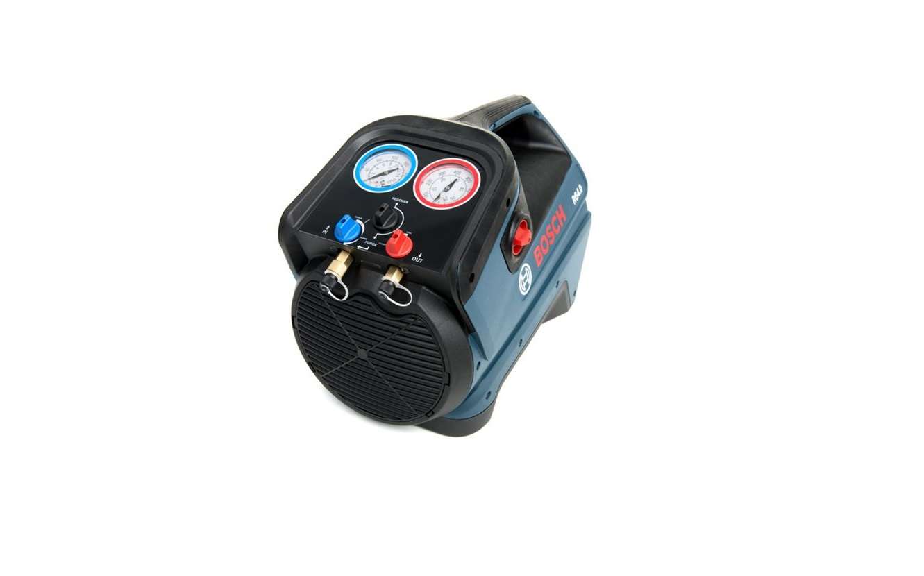
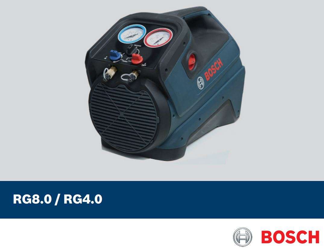
BOSCH RG8.0 & RG4.0 Refrigerant Recovery Unit User Manual
1. Symbols used
1.1 In the documentation
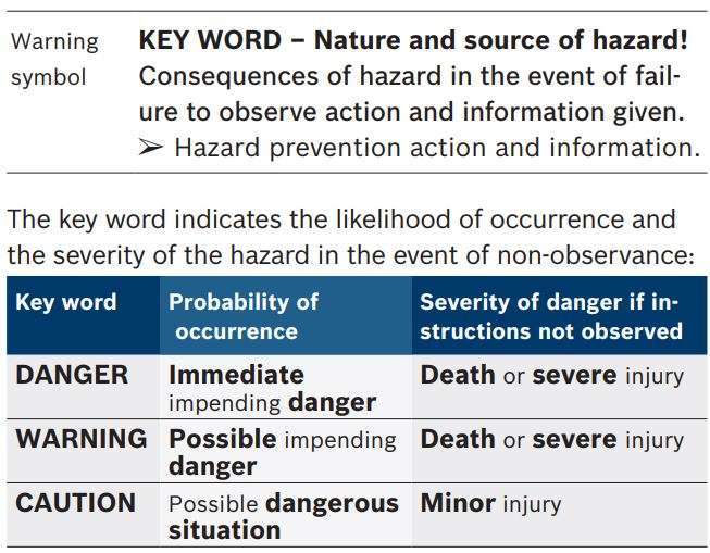
1.1.1 Warning notices Structure and meaning
Warning notices warn of dangers to the user or people in the vicinity. Warning notices also indicate the consequences of the hazard as well as preventive action. Warning notices have the following structure:
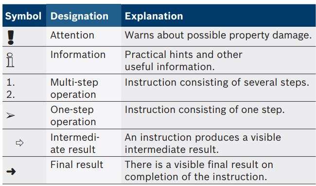
1.1.2 Symbols in this documentation
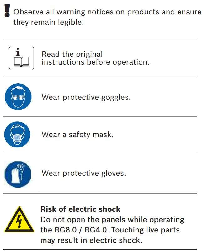
1.2 On the product
2. User information
ℹ Bosch reserves the right to change, update or modify the original instructions at any time without prior notice.
2.1 User group
The RG8.0 / RG4.0 must be used only by a qualified refrigerant service technician, trained in handling of refrigerants, personal protective equipment, refrigerant leakage prevention, handling of cylinders, charging, leak detection and proper disposal. All work conducted on pressurized equipment should be performed by persons with sufficient knowledge and experience in using pressurized devices. Those persons should also be aware of the risks and requirements involved in the use of pressurized devices.
2.2 Warranty
The RG8.0 / RG4.0 is warranted to be free from defects in workmanship, materials, and components for a period of one year from date of purchase. The following conditions apply:
- The limited warranty applies to the original purchaser only.
- The warranty applies to the RG8.0 / RG4.0 in normal usage situations only, as described in the original instructions. The RG8.0 / RG4.0 must be serviced and maintained as specified.
- If the RG8.0 / RG4.0 fails, it will be repaired or replaced at the option of the manufacturer.
- Warranty service claims are subject to authorized inspection for product defect(s).
- The manufacturer shall not be responsible for any additional costs associated with a product failure including, but not limited to, loss of work time, loss of refrigerant, cross-contamination of refrigerant, and unauthorized shipping and/or labour charges.
- All warranty service claims must be made within the specified warranty period. Proof-of-purchase date must be supplied to the manufacturer.
This limited warranty does not apply if:
- The product, or product part, is broken by accident.
- The product is misused, tampered with, or modified.
- The product is used for recovering any substance other than the specified refrigerant types. This includes, but is not limited to, materials and chemicals used to seal leaks in A/C or refrigeration systems.
- The RG8.0 / RG4.0 is used to service A/C or refrigeration systems with refrigerant types other than those specified in chapter 10.
ℹ For more information on the terms and conditions for the sale of goods and services, visit www.atp-europe.de.
3. Safety instructions
All safety instructions are to be read thoroughly before using the RG8.0 / RG4.0 and they must be observed.
ℹ If you are not a qualified refrigerant service technician, do not use this equipment.
ℹ Wear proper Personnel Protective Equipment (PPE) when working on A/C or refrigeration systems.
- The RG8.0 / RG4.0 must be used for the intended purpose.
- Before turning off the RG8.0 / RG4.0, ensure that recovery is complete.
- Refrigerant extracted from the A/C or refrigeration system might be contaminated with moisture, lubricant, dirt and traces of other gases. Use the filter drier supplied with the RG8.0 / RG4.0 to avoid contamination.
- Ensure that you use the RG8.0 / RG4.0 only with the refrigerant types listed in chapter 10. Also, ensure that refrigerants do not mix. The RG8.0 / RG4.0 does
not have any refrigerant identifier system and will not shut off if refrigerants are mixed or, if refrigerant types other than those listed in chapter 10 are used. - Observe the
 symbol on the packaging box. Always ensure that the RG8.0 / RG4.0 is transported in the recommended position.
 - There are no additional safety provisions for protecting the RG8.0 / RG4.0 against damage in the event of natural calamities like earthquakes, fires, floods etc.
- After each use, the RG8.0 / RG4.0 needs to be purged. Make sure there is no residual refrigerant left in the RG8.0 / RG4.0.
- Failure to purge the residual refrigerant from the RG8.0 / RG4.0 could result in:
– Refrigerant mixing on the next use of (the RG8.0 / RG4.0.) equipment.
– The acidic degradation of internal components, ultimately causing premature failure of the unit. - Before the use of the RG8.0 / RG4.0, make sure there is free air flow through the louvres. Blockage of louvres may overheat the motor and might damage the RG8.0 / RG4.0.
- Before using the RG8.0 / RG4.0 read the Material Safety Data Sheets (MSDS) on all the compounds of the refrigerants and refrigerant oils being used.
- If moisture enters the refrigerant system, it is likely to cause damage. Keep everything connected with the refrigerant system thoroughly dry and clean.
- The RG8.0 / RG4.0 should be used in locations with mechanical ventilation providing at least four air changes per hour. Otherwise, the equipment should be placed at least 50 cm above the floor.
- To reduce the risk of fire, avoid the use of extension cords as they may overheat. If you must use an extension cord, it should be a minimum of 14 AWG and maximum length of the wire should be 7.5 m.
- Always connect to a properly grounded electrical supply.
![]() Danger: Risk of injury due to high pressure. If valves are opened quickly, high pressure refrigerant can escape and cause frostbite/ injury.
Danger: Risk of injury due to high pressure. If valves are opened quickly, high pressure refrigerant can escape and cause frostbite/ injury.
Open service and tank valves slowly.
- Use the outlet pressure gauge and weighing scale to check and avoid pressure build up. All connections to the RG8.0 / RG4.0 should be made via a manifold gauge set in order to properly control flow and monitor pressures.
- Always open service and tank valves slowly. This allows quick control of the flow of refrigerants if there is any danger. Once it is determined that there is no danger, the valves may be opened fully.
- Avoid refrigerant coming into contact with skin. The low boiling point of refrigerants can cause frostbite. In case of contact with skin, remove affected clothing immediately and rinse the affected area of skin with plenty of water.
⚠ Do not breathe in refrigerant or oil vapours. The vapours can irritate the eyes and the breathing passage of the nose. If liquid refrigerant/oil gets into the eyes, rinse the eyes thoroughly with water for 15 minutes. Seek medical attention, even if the eyes do not hurt.
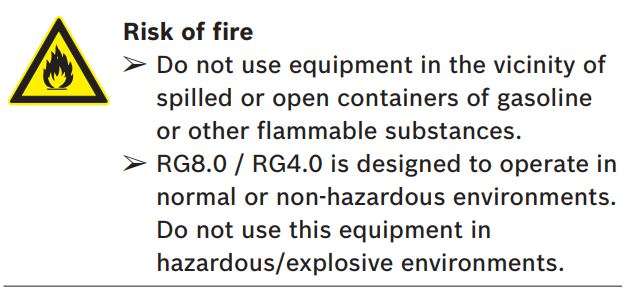
⚠ Do not mix air with refrigerant. Some mixtures of air and refrigerant are flammable at high pressure. These mixtures are potentially hazardous and can cause fires or explosions resulting in damage to property and injury to people.
- Some refrigerant may not be used in environments with a risk of explosion. Fire, naked flames and smoking are prohibited. No welding or soldering is allowed. High temperatures and UV radiation may cause refrigerant to chemically separate. The resulting products cause cough and nausea.
- Refrigerants should never be mixed within a system. Comply with your local regulations for handling and storing of recovered refrigerant.
- Additionally, recovery tanks should always be placed on a refrigerant scale to monitor the filled quantity.
- Use only approved tanks with a minimum of 41 bar working pressure that comply with local regulations.
- Recovery tanks are designed for different pressures. Do not exceed the working pressure of each tank.
- Never transport an overfilled tank. Safety codes recommend that hermetically sealed tanks should not be filled more than 80% of its capacity with liquid. The remaining 20% is called head pressure room. Refrigerant expands when temperature increases and may cause a tank to explode if overfilled. Refer to the following table:

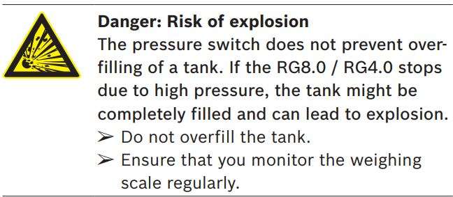
- A scale must be used to avoid overfilling the storage tank.
- Cover the ports of the storage tank with caps to prevent refrigerant leakage.
- Tanks and filters should be designated for one refrigerant only and clearly marked as to which refrigerant they contain and/or are designated for use with. Refrigerants should never be mixed within a system. Comply with your local regulations for handling and storing of recovered refrigerant.
- Special care should be taken when recovering from a burned-out compressor. Use two high capacity acid filters, in series. Bosch recommends using Alco® type EK-162-F or Sporlan® type C-162-F.
- The RG8.0 / RG4.0 can be used only in a sheltered or indoor environment.
3.1 Safety devices
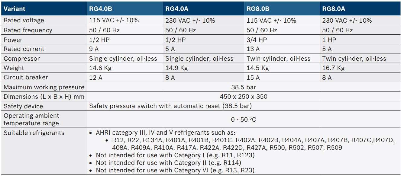
- Pressure switch – Cuts off the power supply to the motor if the normal operating pressure exceeds 38.5 bar.
- Circuit breaker – Terminates the power supply in case of over current drawn by the RG8.0 / RG4.0 .
4. Product description
4.1 Application
The RG8.0 / RG4.0 recovers refrigerant from A/C or refrigeration system and pumps to an external refrigerant storage cylinder.
4.2 Scope of delivery
Description
Recovery unit RG 8.0 or RG 4.0
Power cable
Filter drier
Filter hose
Original instructions
4.3 Description of unit

- Inlet port
- Inlet control valve
- Recovery / purge valve
- Outlet control valve
- Inlet pressure gauge
- Outlet pressure gauge
- Handle
- Main switch
- Louvres
- Outlet port
- Circuit breaker
- Power receptacle
4.3.1 Inlet and outlet ports
- Inlet port (Fig. 1, Pos. 1)- Used to connect the
RG8.0 / RG4.0 to an A/C or refrigeration system via a filter. - Outlet port (Fig. 1, Pos. 10)- Used to connect the RG8.0 / RG4.0 to the refrigerant tank.
4.3.2 Control valves
- Inlet control valve (Fig. 1, Pos. 2) – Used to:
– control the inflow of refrigerant during recovery in gas or liquid phase
– purge residual refrigerant from the RG8.0 / RG4.0 - Outlet control valve (Fig. 1, Pos. 4)
– Used to control the outflow of the refrigerant from the RG8.0 / RG4.0 to the refrigerant tank - Recovery / purge valve (Fig. 1, Pos. 3) – Used to:
– recover refrigerant from the A/C or refrigeration system to the refrigerant tank
– purge residual refrigerant from the RG8.0 / RG4.0
4.3.3 Inlet and outlet pressure gauges
- Inlet pressure gauge (Fig. 1, Pos. 5) – Measures the pressure at the inlet of the RG8.0 / RG4.0.
- Outlet pressure gauge (Fig. 1, Pos. 6) – Measures the pressure at the outlet of the RG8.0 / RG4.0
4.3.4 Main switch
The main switch (Fig. 1, Pos. 8) allows you to power on / off the RG8.0 / RG4.0.
4.3.5 Circuit breaker
If the current drawn by the RG8.0 / RG4.0 exceeds safe levels, then the power supply will be cut off by a circuit breaker. The circuit breaker can be manually reset every time the power is cut off. Do not reset the circuit breaker unless the power is switched off. Refer to chapter 10 for the circuit breaker rating.
5. Commissioning
5.1 Removing the transport packaging
- Remove the transport packaging.
- Check if all items have been delivered as per chapter 4.2.
- Check the RG8.0 / RG4.0 for damages. If there are damages, contact Bosch customer service.
5.2 Before turning on for the first time
- Read the manual.
- Remove the caps from the hose.
- Connect the filter to the filter hose. Ensure that the arrow on the filter points towards the inlet port of the RG8.0 / RG4.0.
- Connect the filter hose to the inlet port.
- Ensure that all the valves are closed.
6. Operation
6.1 Refrigerant recovery
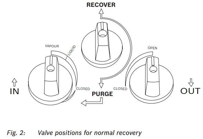
6.1.1 Valve positions for normal recovery
6.1.2 Normal recovery
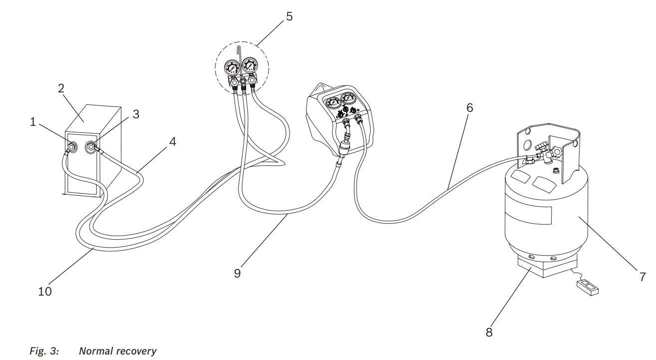
- Liquid port/ High side port
- A/C or refrigeration system
- Vapour port / Low side port
- Vapour/ Low side hose
- Manifold gauge set with optional sight glass
- Outlet hose.
- Refrigerant tank.
- Weighing scale
- Inlet hose
- Manguera de líquido/ lado alto
ℹ The sight glass provides a method of determining the
state (liquid or vapour) of the system’s refrigerant and the presence of contamination in it
- Disconnect the power supply to the A/C or refrigeration system.
- Connect the RG8.0 / RG4.0 to a mains power supply that matches the voltage and frequency rating on the RG8.0 / RG4.0.
- Before making any hose connections, ensure that A/C or refrigeration system service valves, manifold gauge set valves, recovery unit control valves and recovery tank valves are all in the closed position. Also, make sure that the recovery / purge valve is in the RECOVER position (pointed upwards). Refer to Fig. 2.
- Connect the RG8.0 / RG4.0 to the system being serviced according to Fig. 3. Follow the order outlined below. Use only designated refrigerant hoses that meet local regulations. It is strongly recommended to use hoses with manual shutoff valves on one end, and these instructions are written for such hoses.
– Always use a service manifold gauge set between the A/C or refrigeration system, recovery unit and auxiliary device(s).
– Ensure that air has been removed from the hoses and the RG8.0 / RG4.0.
– Connect a hose with the shut-off valve end to the low side (vapour) service port of the A/C or refrigeration system and the other end to the low side port of the manifold gauge set.
– Connect a hose with the shut-off valve end to the high side (liquid) service port of the A/C or refrigeration system and the other end to the high side port of the manifold gauge set.
– Connect the utility port of the manifold gauge set to the recovery unit inlet fitting, with the shut-off valve end of the hose at the machine inlet, ensuring that an inline filter drier is used.
– Connect an approved refrigerant recovery tank to the outlet port of the RG8.0 / RG4.0 with the shut-off valve end of the hose at the tank, and place the tank on an appropriate weighing scale. If the tank has two valves / ports, one for liquid and one for vapour, connect to the liquid port. - Open the A/C or refrigeration system’s low side (vapour) and high side (liquid) service ports and the shut-off valves on the hoses connected to the manifold gauge set. Always open valves slowly to check hoses and connections for leaks.
- Open the manifold gauge set (blue) low side valve and the shut-off valve on the hose to the inlet port of the RG8.0 / RG4.0.
- Open the inlet valve (blue) of the RG8.0 / RG4.0 fully, by rotating the knob counter-clockwise, that is to the VAPOUR position.
- Open the outlet valve (red) of the RG8.0 / RG4.0 fully.
- Open the shut-off valve on the hose connected to the recovery tank and then open the recovery tank valve (only the one connected to the RG8.0 / RG4.0).
- If there is pressure differential between the A/C or refrigeration system and the tank, refrigerant vapour will begin to flow.
- Turn the recovery machine Inlet (blue) control valve to the LIQUID marking on the front panel, refer to Fig 2. Rotate the Master Switch to the ON position to start the recovery.
ℹ If you have trouble starting or re-starting the RG8.0 / RG4.0 due to high head pressure, first power off the unit. Close the inlet valve and then slowly turn the inlet valve towards the PURGE position until the inlet pressure rises. Close the inlet valve again and re-start RG8.0 / RG4.0. - Slowly open the manifold gauge set high side (red) valve, and close the manifold gauge set low side (blue) valve.
- Liquid refrigerant should begin to flow. If knocking or hammering is heard, throttle back the blue inlet valve (towards the closed position) of the RG8.0 / RG4.0. Running the RG8.0 / RG4.0 with the valve open too far during liquid recovery may cause knocking / hammering and possible damage to the RG8.0 / RG4.0.
- Once all liquid has been transferred from the A/C or refrigeration system to the recovery tank, and only vapour is being recovered, the inlet (blue) valve of the RG8.0 / RG4.0 may be opened fully, and the blue low side valve of the manifold may be opened again to speed the remaining recovery.
- Continue recovery until satisfactory vacuum level has been reached. The RG8.0 / RG4.0 will cut-off automatically when inlet pressure reaches minimum required vacuum.
- Upon completion of recovery:
– Close the A/C or refrigeration system service valves and shut-off valves on the connected hoses.
– Close the manifold service valves.
– Close the inlet (blue) valve on the RG8.0 / RG4.0.
– Switch off the RG8.0 / RG4.0.
– Proceed to purge RG8.0 / RG4.0 as directed in chapter 6.2.
ℹ The RG8.0 / RG4.0 is equipped with a vacuum switch which will cut-off the RG8.0 / RG4.0 automatically when inlet valve is closed or inlet pressure reaches minimum required vacuum.
ℹ After completion of recovery, if the RG8.0 / RG4.0
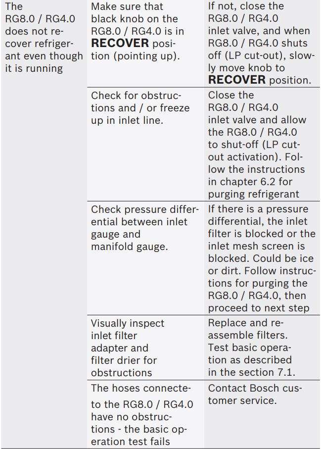
stops due to low inlet pressure and the A/C / refrigeration system has refrigerant left in it, the RG8.0 / RG4.0 will restart automatically if a significant pressure rise is detected.
ℹ To maximize recovery rates use the shortest possible length of 3/8″ or larger hose. A hose not longer than 1 meter is recommended. Always remove all unnecessary hose core depressors and Schrader valves from port connections (using the proper valve core tool) for maximum throughput. Deformed rubber seals and core depressors in hoses and faulty or unnecessary Schrader valves can restrict flow by up to 90%.
6.1.3 Push / pull method
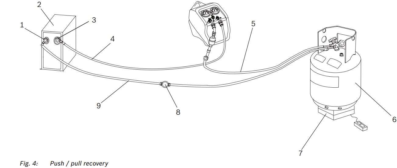
- Liquid port/ High side port
- A/C or refrigeration system
- Vapour port / Low side port
- Vapour/ Low side hose
- Inlet hose
- Refrigerant tank.
- Scale
- Sight glass
- Liquid/ High side hose
ℹ The push / pull method works with large systems where liquid refrigerant is readily accessible. Do not use this method on systems that contain less than 7 kg of refrigerant. It is not possible to completely empty a system using the push / pull method. After liquid is removed, it will be necessary to switch connections and follow the procedure for normal recovery to remove remaining refrigerant from the A/C or refrigeration system.
! When using the push / pull method, you must use a scale to prevent overfilling the storage tank. Once the push / pull siphon is started, it can continue and overfill the storage tank even if the tank is equipped with a float level sensor. The siphon can continue even when the RG8.0 / RG4.0 is turned off. You must manually close the valves on the tank and the RG8.0 / RG4.0 to prevent overfilling the recovery tank.
- Disconnect the power supply to the A/C or refrigeration system.
- Connect the RG8.0 / RG4.0 to a mains power supply that matches the voltage and frequency rating on the RG8.0 / RG4.0.
- Before making any hose connections, ensure that system service valves, recovery unit control valves and recovery tank valves are all in the closed position. Also, make sure that the recovery / purge valve is in the RECOVER position (pointed upwards). Refer to Fig. 2.
- Connect the RG8.0 / RG4.0 to the system being serviced according to Fig. 4. Follow the order outlined below. Use only designated refrigerant hoses that meet local regulations. Because hoses must be switched in order to remove refrigerant from the system, it is necessary to use hoses with manual shutoff valves on both ends, and these instructions are written for such hoses.
– Ensure that air has been removed from the hoses and the RG8.0 / RG4.0.
– Connect a hose to the vapour port of an approved two-valve recovery tank and the other end to the inlet port of the RG8.0 / RG4.0.
– Connect a hose to the liquid port of an approved two-valve recovery tank and the other end to the high side (liquid) service port of the A/C or refrigeration system. It is beneficial to have a sight glass (Fig. 4, Pos. 8) in this hose to monitor liquid refrigerant flow.
– Connect another hose from the low side (vapour) service port of the A/C or refrigeration system to the outlet port of RG8.0 / RG4.0. - Open the high and low side service ports of the A/C or refrigeration system and shut-off valves in the hoses. Always open valves slowly to check hoses and connections for leaks!
- Open the recovery tank vapour valve, then open inlet control valve of the RG8.0 / RG4.0 by rotating the knob (blue) counter-clockwise towards VAPOUR position.
- Open the outlet control valve and the recovery tank liquid valves of RG8.0 / RG4.0.
- Start the RG8.0 / RG4.0. Liquid refrigerant should begin to flow into the tank. This can be verified with the sight glass. Refer to Fig. 4, Pos. 8.
- Continue to run RG8.0 / RG4.0 until the liquid refrigerant is removed from the system. Once the liquid refrigerant has been transferred from the A/C or refrigeration system to the recovery tank and only vapour is being recovered, it is necessary to switch to normal recovery connections and procedure as outlined in chapter 6.1.2.
- Close the inlet valve of the RG8.0 / RG4.0 and the refrigerant tank liquid valve. The RG8.0 / RG4.0 should shut-off due to the low-pressure cut-off switch.
- Power off the RG8.0 / RG4.0 and close all remaining valves outlet valve of the RG8.0 / RG4.0, system service valves and recovery tank vapour valve.
- Close all hose shut-off valves and proceed to reconnect and follow the procedure as outlined in chapter 6.1.2.
6.2 Purging residual refrigerant
Upon completion of recovery as defined in chapter 6.1.2, the RG8.0 / RG4.0 must be purged.
- Ensure that the ports of the system being serviced are closed.
- Ensure that the inlet control valve of the RG8.0 / RG4.0 is in the CLOSED position.
- Ensure that the RG8.0 / RG4.0 is powered off.
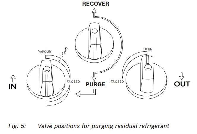
- Turn the recovery / purge (Black) knob of RG8.0 / RG4.0 to PURGE position (pointed downwards) as shown in Fig. 5.
- Start the RG8.0 / RG4.0 and slowly turn the inlet (Blue) control valve of the RG8.0 / RG4.0 to PURGE position as shown in Fig. 5. The RG8.0 / RG4.0 starts purging automatically.
- Run until desired vacuum is achieved or until low pressure switch cuts off the RG8.0 / RG4.0.
- Close the valve on the recovery tank, then the outlet control valve of the RG8.0 / RG4.0.
- Power off the RG8.0 / RG4.0.
- Turn the inlet control valve to the closed position.
- Close all hose shut-off valves, then disconnect and store the hoses.
6.3 Purging Non-Condensable Gases (NCGs)
! This procedure may be prohibited in certain localities. Check local regulations and guidelines to determine if your location allows purging of NCGs before performing any such procedure.
- Keep the tank in a steady state for 24 hours which allows NCGs to rise to top of the tank.
- Connect a manifold gauge set to the tank.
- Open the tank valve to which the gauge is connected and read the pressure.
- Determine the ambient temperature.
- Refer to a refrigerant pressure / temperature chart. Find the temperature on the chart and look across to the corresponding pressure for the type of refrigerant in the tank. Compare how that relates to the reading on the gauge.
- If the pressure reading is higher than the pressure shown on the chart, slowly open the vapour port valve. Ensure the pressure on the pressure gauge decreases. To prevent venting, add 0.3 – 0.35 bar to the pressure shown on the chart. When the gauge corresponds to that pressure, close the vapour port valve.
- Keep the tank in a steady state for 10 minutes and check the pressure again.
- Repeat the process if necessary.
7. Troubleshooting
7.1 Basic operational test
! Basic operational test should only be done if there is a serious breakdown or fault in the system component.
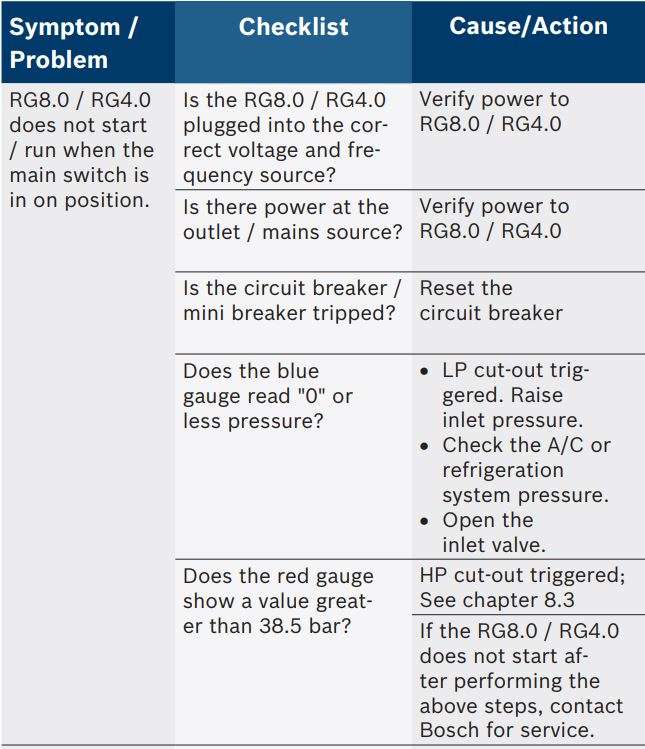
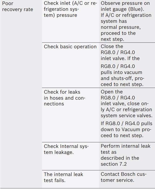
Basic operational test can validate proper function of the RG8.0 / RG4.0 and point to external issues if problems are experienced. With nothing connected to the RG8.0 / RG4.0 and recovery / purge valve (black) in the RECOVER position, open the inlet control valve (blue) and outlet control valve (red) valves. Start the RG8.0 / RG4.0 and close the inlet valve. The RG8.0 / RG4.0 should shut-off due to Low Pressure (LP) cut-out. Upon opening the inlet valve, the RG8.0 / RG4.0 should restart. Upon closing the outlet valve, the RG8.0 / RG4.0 should begin to pump up pressure on the High Side (red) gauge. When the pressure reaches approximate 38.5 bar, the RG8.0 / RG4.0 should shut off due to High Pressure (HP) safety switch. Slowly open the outlet valve and the RG8.0 / RG4.0 should restart when pressure drops below 28 bar. This process validates normal and correct operation of all features.
7.2 Internal leak test
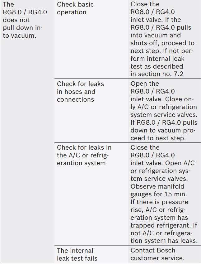
In the event that internal leakage is suspected the following test can be performed to confirm or deny.
- With nothing connected to the RG8.0 / RG4.0, ensure the recovery / purge valve is in the RECOVER position.
- Open the inlet valve and close the outlet valve.
- Start the RG8.0 / RG4.0 and allow it to run until it shuts off due to HP cut-out.
- Close the inlet valve. Blue gauge should indicate zero bar and high approximately 38.5 bar.
- Slowly turn the recovery / purge valve from RECOVER to PURGE position. The pressure should drop on the red gauge and rise on the blue gauge, settling at approximately equal values.
Note the values and watch the gauges for change over the next 30 seconds. If there is no significant pressure drop on either side, the internal integrity is confirmed.
8. Maintenance
8.1 Spare and wearing parts

8.2 Replacing the filter drier
- Make sure the RG8.0 / RG4.0 is switched off and disconnected from mains supply before proceeding.
- Ensure that residual refrigerant in the RG8.0 / RG4.0 is purged. Refer to section 6.2
- Ensure that the inlet and outlet valve pressure is zero.
- Remove the inlet hose if still connected to the A/C or refrigeration system.
- Uninstall the filter drier.
- Replace with a new filter drier (order number 100343).
8.3 Resetting the high pressure switch
- Make sure the RG8.0 / RG4.0 is switched off.
- Check if the recovery tank is overfilled.
- Close the recovery tank valve(s), the hose shut-off valve(s) connected to the tank, and the inlet and outlet control valves of the RG8.0 / RG4.0.
- Disconnect the hose(s) only from the recovery tank. Retain the hose connections to the RG8.0 / RG4.0.
- Connect the hose(s) to another recovery tank which is empty.
- Open the recovery tank valve(s).
- Open the outlet control valve of the RG8.0 / RG4.0.
- Open the shut-off valve in the hose connected to the recovery tank liquid port and allow refrigerant to flow and pressure on the outlet side of the RG8.0 / RG4.0 to drop.
- Once the pressure in the outlet of RG8.0 / RG4.0 drops below 28 bar, switch on the RG8.0 / RG4.0.
- When the RG8.0 / RG4.0 restarts, slowly open the inlet control valve of the RG8.0 / RG4.0 and resume recovery. If in push / pull configuration, it will also be necessary to open the shut-off valve on the hose connected to the vapour port of the tank.
ℹ Once the safety pressure switch is activated, it will remain open until the pressure within the RG8.0 / RG4.0 is reduced below 28 bar, at which time it will automatically reset. It is not possible to operate the RG8.0 / RG4.0 until this occurs.
9. Decommissioning
9.1 Disposal of electronic items
This product is subject to European guidelines 2002/96/EG (WEEE). R Old electrical and electronic devices, including cables and accessories or batteries must be disposed of separate from household waste.
- Use the return and collection systems in place for disposal in your area.
- Damage to the environment and hazards to personal health can be prevented by properly disposing of old equipment.
- Follow local regulations for disposal of electronic items.
9.2 Disposal of refrigerants and oils
Refrigerants that can no longer be used must be handed over to the gas suppliers for disposal. The oils recovered from the A/C or refrigeration system must be disposed in accordance with local regulations. Refrigerants which are unknown must be disposed in accordance with local regulations. Contact local refrigerant suppliers or competent authorities for information regarding handling and disposal of refrigerants and lubricants.
9.3 Disposal of filter drier
Dispose the filter drier through the designated return points or in accordance with local regulations.
10. Technical data
11. Overview of parts
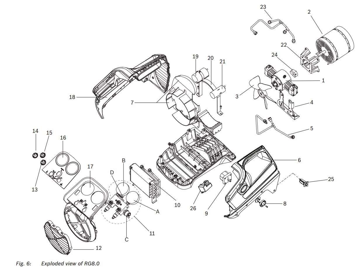
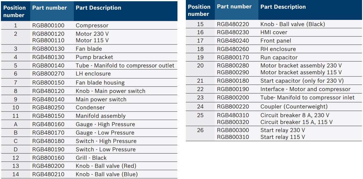
11.1 Parts list – RG8.0
11.2 Parts list – RG4.0
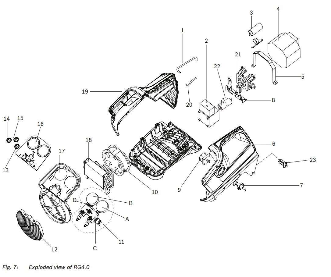
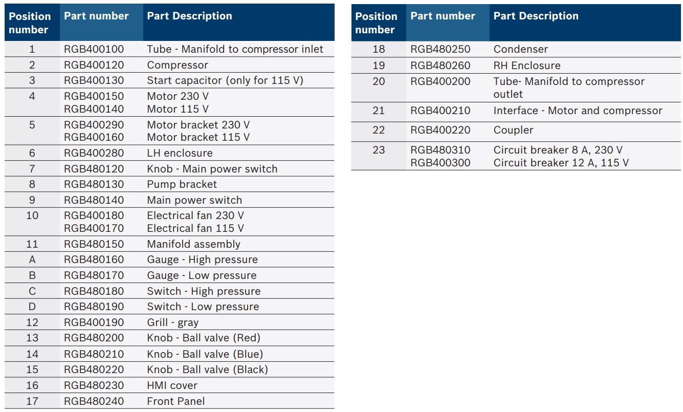
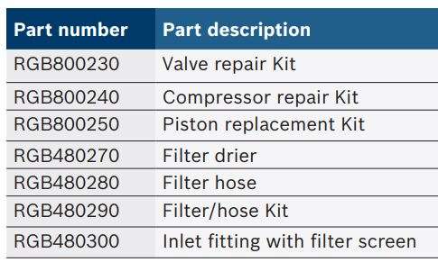
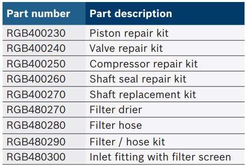
11.3 Additional parts / Kits
11.3.1 For RG8.0
11.3.2 For RG4.0
Bosch Automotive Service Solutions GmbH
Luerriper Strasse, 62
Moenchengladbach 41065
DEUTSCHLAND
www.atp-europe.de
[email protected]
Download PDF
BOSCH RG8.0 & RG4.0 Refrigerant Recovery Unit User Manual PDF Download
