FDJ FCA Style 14-36 Ford Dismantling Joint User Manual

- Remove plastic ties from assembly.
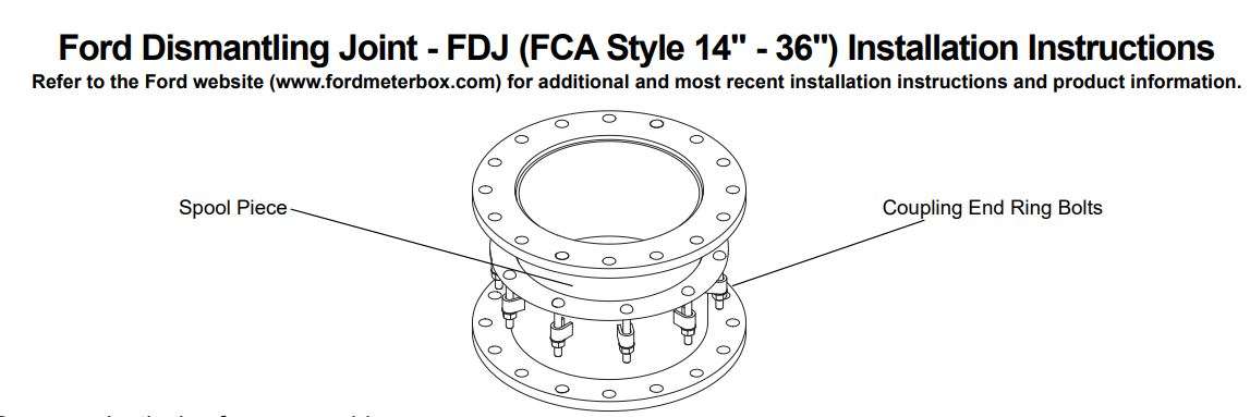
- Inspect all FDJ parts to ensure no damage has occurred. Verify the mating flanges to ensure they match the FDJ drilling. Verify the space requirements for the dismantling joint to function properly. The spool piece must remain inserted a minimum of 2 inches into the flange coupling body at final assembly.
- Loosen the end ring bolts to allow the FDJ to expand and contract freely.
- Position the contracted FDJ between the mating flanges Insert flange gaskets (not provided) between the flange faces. Using flange bolts (not provided), connect the flange coupling body to the mating flange.
- Properly block and shim all components for proper safety and alignment.
- Expand the FDJ and attach to the opposite mating flange using flange bolts.
- Tighten all end ring bolts finger tight. Evenly tighten bolts in an alternating pattern being certain the end ring remains parallel to the flange and perpendicular to the center line of the pipe. Complete tightening to 75 80 ft-lbs. of torque.
- Recheck the torque on all bolts after pressurization of the line.

- Remove plastic ties from assembly.
- Inspect all FDJ parts to ensure no damage has occurred. Verify the mating flanges to ensure they match the FDJ. Verify the space requirements for the dismantling joint to function properly. The spool piece must remain inserted a minimum of 2 inches into the flange coupling body at final assembly.
- Loosen the enduring bolts to allow the FDJ to expand and contract freely.
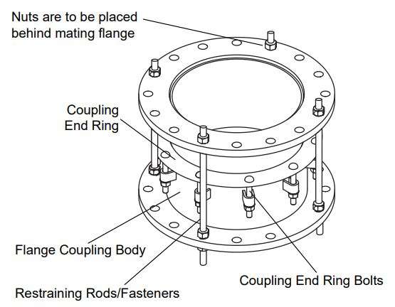
- Position the contracted FDJ between the mating flanges. Insert flange gasket (not provided) between the flange faces. Using flange bolts (not provided); connect the flange coupling body to the mating flange. Make sure to leave open the required amount and location of holes to accommodate the tie-rods. The tie-rods must be evenly spaced around the circumference of the flanges.\
- Properly block and shim all components for proper safety and alignment.
- Expand the FDJ and attach to the opposite mating flange using flange bolts.
- Insert the tie-rods into the holes remaining open when securing the flange. Make sure to thread one nut onto each end of the rod prior to fully inserting through both flanges. Each end of the rods must pass entirely through the mating flanges on each end. (The rods do NOT go through the coupling end ring.) Use restraining fasteners to set position. Snug inner and outer nuts against the flange surfaces. Hold one nut and tighten the other nut to applicable torque. Tighten the tie-rod nuts to 75-80 ft-lbs of torque.
- Tighten all coupling end ring bolts finger tight. Evenly tighten bolts in an alternating pattern being certain the coupling end ring remains parallel to the flange and perpendicular to the center line of the pipe. Complete tightening to 75-80 ft-lbs. of torque.
- Recheck the torque on all bolts after pressurization of the line.
The Ford Meter Box Company, Inc. P.O. Box 443, Wabash, IN 46992-0443 Phone: 260-563-3171 / FAX: 800-826-3487
Download PDF
FDJ FCA Style 14-36 Ford Dismantling Joint User Manual PDF Download

 www.fordmeterbox.com