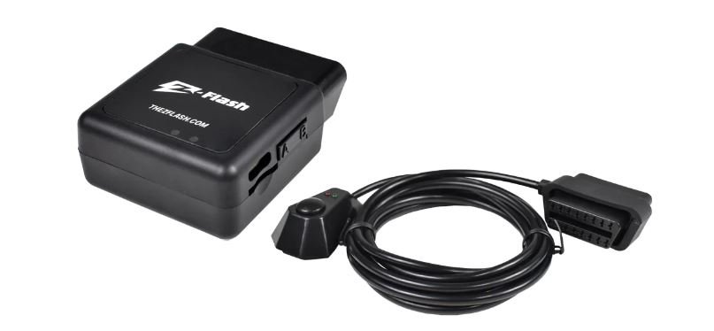
Z-Flash ZF-C-OBDFM-S Vehicle Flasher Module User Manual
Warranty:
This warranty protects the product(s) specified to be free from defects in material and workmanship for 2 (two) years. During the warranty period we will, at our sole discretion, repair or replace the product(s). This limited warranty does not cover travel expense or labor charges for the removal and reinstallation of the product, or any other charges alike. We are not responsible for incidental damages, including but not limited to: loss of time, loss of work, inconvenience, loss and/ or damage to personal property, shipping expenses. We are in no way responsible for any loss or any indirect or consequential damages resulting from any such defect in material and/ or workmanship whether it’s due to negligence, incorrect installation, or manufacturer mistake. It is the sole responsibility of the party initiating a warranty claim to pay shipping charges associated with returning a product.
⚠ Warning:
- If you do not know what you are doing, do not try.
- We advise professional installation for all products.
- Electrical shock can cause injury or death. Please use proper tools and protection when installing. Professional installation is strongly advised.
- Please check for correct installation method before powering on. Electrical fire can occur.
- Do not run any wires in the way of air bags or other safety devices.
- Please check with your local laws to ensure this module is legal in your area.
INSTALLATION INSTRUCTIONS
Please read all of the instructions before you begin your installation.
- Disconnect your vehicle’s battery before installing your module. If your F-Series truck has two batteries, be sure to disconnect both.
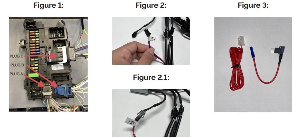
- Open the fuse box panel located in the passenger side footwell to gain access to the vehicle’s body control module (BCM). See Figure 1 for location.
- Remove factory plug A from the BCM and plug in the Z-Flash plug A into that socket. Then plug factory plug A that you removed into the Z-Flash adapter plug A.
- Remove factory plug B from the BCM and plug in the Z-Flash plug B into that socket. Then plug factory plug B that you removed into the Z-Flash adapter plug B.
- Remove factory plug C from the BCM and plug in the Z-Flash plug C into that socket. Then plug factory plug C that you removed into the Z-Flash adapter plug C.
- Connect the remaining 10 outputs into their respective leads on the flasher module in any order.
- There are two ways to activate the module; with the provided switch or hard-wiring it into your own controller or the vehicle’s up fitter switch. See the chart below for instructions.
- After installing your Z-Flash module, reconnect your vehicle’s battery.
| Switch | Hardwire |
| Plug the provided switch into the flasher and turn on to activate. | Locate the bag with the red wire (see Figure 3). One end has a 4-slot connector that plugs into the Z-Flash and the other end is bare wire that ties to a switch. If you need to switch patterns, simply plug the red momentary switch into the other Z-Flash port that takes the 2-slot plug. |
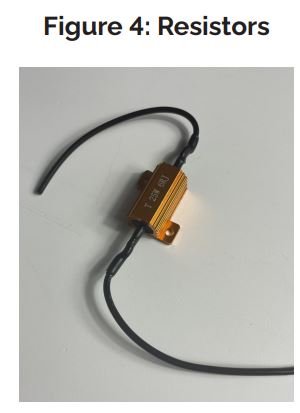 If you have non-factory LED bulbs, or if you’re getting a hyper flash condition after installation, the resistors need to be installed on the lights that are having that issue.
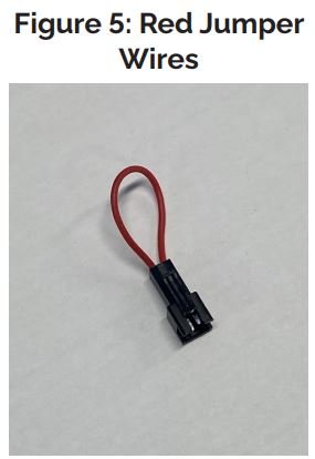 These are used when you want to disable certain lights from flashing.
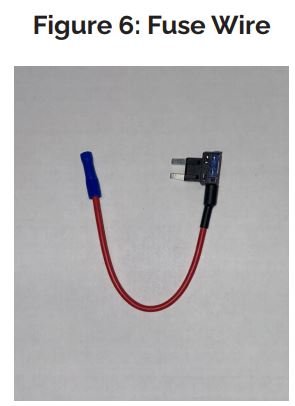 This fuse wire is not needed unless you’re hardwiring your module to an external switch.
